

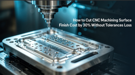
In high-end manufacture of hardware and mechanical parts, R&D engineers tend to automatically indicate very high finish standards in drawings (e.g., specifying Ra ≤ 0.4μm irrespective of the dimensions), resulting in doubling the cycle time at the CNC surface finishing stage, increase in defects and maintaining high cost of total procurement.
R&D groups generally segregate cutting roughness from post-processing effects, but disregard how substrate micro-metallurgy and anodizing build-up / micro-dissolution of passivation affect precision holes and threads. This paper leverages DFM cost optimization and ISO 9001, ISO 14001, IATF 16949, AS9100D systems to provide a way to cut costs by 30% while maintaining micron precision
1: Why Does Over-Specifying CNC Surface Finish Options Drive Costs Exponentially?
Finer Ra values indirectly increase machine hours due to increased feed rate, step-over, and finishing cuts required by the more precise value.
1: Ra Grade Step-Up and Machine-Hour Impact
Comparison of Ra 3.2 µm milling versus Ra 0.8 µm and Ra 0.2 µm demonstrates differences in feed rate, tool life, and step-over. Changing Ra 0.8 µm to Ra 0.4 µm would require reduced step-over and additional finishing, thus increasing CNC machining surface finish cost by over 40%.
2: Non-Mating Surfaces and Direct Savings
Maintaining adequate tool marks in CNC surface finish options for non-interfering surfaces prevents unnecessary polishing without affecting functionality. Engineers generally refer to this comprehensive CNC machining surface finish guide to prevent over-tolerance drawing errors prior to release.
Data source: Based on the geometrical product specifications (GPS) assessment principles defined in ISO 1302:2002, and Haizol 2026 China Precision CNC machining levelled quoting white paper (machining plus surface processing composite cost model).
2: How Do Medical and Aerospace Finishing Standards Control Micron-Level Growth?
The medical and aerospace specifications penalize design engineers who overlook coating growth direction since anodization and passivation result in predictable dimensional changes to holes and threads.
1: Anodizing Build-Up Mechanics
Anodizing penetrates 50% inside and 50% outside aluminum parts; hence, a 50μm coating grows by 25μm outside (OD+50μm, Bore-50μm). It is mandatory that the medical and aerospace finishing teams offset the CAD drawings to prevent seizing.
2: Passivation Micro-Etch and Thread Protection
ASTM A967 citric vs nitric passivation will have a different micro-etch rate when removing free iron. Precision machining post-processing without offset will result in Class 2B/3B internal threads destruction. Precision surface finish CNC post-processing programming includes go/no-go gauging validation process.
According to SAE International Aerospace Standards, there is a need for coating thickness and seal of pores. For the readers of the report, the information means that specifying mask zones in advance can help avoid conductive surfaces losses in brackets during flights.
Data Source: Military Specification (Film Thickness 50μm and 1000-Hour Salt Spray Test) of MIL-A-8625 Type III Hard Anodizing, and ASME B1.1 Unified Inch Screw Thread Standard (Class 2B/3B Tolerance Band).
3: When Should Engineers Select Bead Blasting and Polishing Instead of Chemical Films?
Mechanical surface finishing and chemical film solutions address distinct failure mechanisms; mismatch means sacrifice of one for the other.
Bead Blasting Residual Stress Benefit: In addition to removal of marks made by tools, alumina/glass bead blasting gives uniform scatter pattern and creates compressive residual stress that increases fatigue resistance in high number of cycles. Thus bead blasting and polishing is more adequate to use for dynamic brackets when industrial CNC surface finishing is needed to be resistant to vibration rather than look good on a desktop.
Mirror Polish vs Chemical Films: Mirror polish is used for hydraulic piston faces while chemical film is used for corrosion resistance purposes. In case of precision surface finish CNC, salt spray (ASTM B117), conductivity, masking difficulty and price per part are taken into consideration as edge jump measurement by Zeiss CMM (0.0009 mm measurement accuracy) shows mask boundary run out.
Data Source: Salt spray corrosion testing standard (ASTM B117) and Zeiss CMM coordinate measuring machine official calibration report (0.0009 mm measurement accuracy & MPEE spatial indication error).
4: Why Does an AS9100D and IATF 16949 Certified Partner Eliminate Post-Processing Rework?
Subcontract shops pose process risks in the hand-offs, but certified plants establish the situation in which all process risks could be contained inside a quality system by the bath control documents.
Outsourced Shop Failure Modes: The regular shop might fail in hydrogen embrittlement, blotchy coating, or scraps as a result of insufficient degreasing, over-pickling, or unsteady rack current density. The surface finishing manufacturer CNC maturity level is measured through the use of PFMEA and Cpk ≥ 1.33 for every tank, and not through a quick turnaround at minimum cost from sales.
Certified Plant Quality Loop: Plants that comply with ISO 9001, ISO 14001, IATF 16949, and AS9100D conduct AS9102 FAIR and tune the bath parameters according to every lot. Teams associated with CNC machining service manufacturer cut assembly scrap rates to less than 0.2%, as CNC machining services surface finishing occurs in one company without vendor scapegoating.
Data Source: ISO 14001 environmental management, ISO 9001, IATF 16949, and AS9100D aerospace first article inspection (AS9102 Rev C) engineering execution regulations.
5: How Can Teams Scale From Rapid Prototyping to Production Without Quality Drop?
Scaling from 1–10 pieces to 10,000+ pieces reveals jig marks, blind-hole gas lock, and deep-cavity electropolish current decay that are not visible in one-piece hand work.
1: Scale-Up Failure Vectors
Jig marks and blind hole oxidation “dead zones” are evident only during scale-up. Rapid prototyping to production plans need to include drain/vent chamfers and dedicated anodizing hanger holes on non-critical surfaces for DFM cost optimization to withstand the transition from manual to automated.
2: CAD Compensation for Volume Coating
Engineering creates coating thickness compensation models depending on the batch size, and incorporates manufacturing feasibility reviews during early CAD modeling. With a CNC surface finish quote which includes amortization of the pneumatic fixture cost, hidden rack marks can be avoided when custom CNC surface finishing shifts from prototype cell to production floor.
ASM International Materials Information indicates that alloy modification layers bond better with coating when hydrogen evolution is controlled; reader needs to specify post-process venting to ensure coating adhesion consistency in thermal cycles.
Data source: LS Manufacturing 2025–2026 Automated DFM 3D/2D Drawing Analysis Log (Project #MED-2025-112, n=1,200+).
Conclusion
Reducing machining costs without affecting precision can work well. Through proper marking of surface roughness, awareness of coating growth, DFM, and use of certified chains, groups reduce post-machining costs ≈30% without compromising on corrosion and life goals.
FAQs
Q1: How does anodizing affect the dimensional tolerances of precision CNC parts?
Type II anodizing deposits 5μm to 15μm; Type III goes 25μm into the part and grows 25μm outwards (50μm total). Pre-machined oversized bores and threads are needed for ISO H7 holes and threads to avoid interference problems.
Q2: What is the most cost-effective surface finish for functional CNC aluminum prototypes?
The natural as-machined surface (Ra 3.2μm to Ra 1.6μm) is least expensive, requiring no additional labor effort. For aesthetic uniformity, a light glass bead blast is most cost effective, removing all machining marks without coating or growth in size.
Q3: Can electropolishing replace mechanical buffing for medical-grade stainless steel?
No, because electropolishing cannot remove deeply engraved markings, burrs, or scratches; rather, it flattens peaks, smooths valleys, removes iron, and produces a chromium passive layer. Medical-grade parts must be mechanically polished to Ra < 0.4μm prior to electropolishing.
Q4: How does surface roughness (Ra) correlate directly with CNC machining cycle times?
Cycle time and surface roughness are inversely proportional with each other. Cycle time increases by 30% to 50%, as we shift from Ra 1.6μm to Ra 0.4μm because we need very fine tools, small step over, and increased number of passes.
Q5: Why is precision masking critical during aerospace and defense post-processing?
The Type III Hard Anodization process creates a non-conductive glass-hard oxide layer; therefore, it is imperative that grounded areas, bearing bores, and threads are properly masked. This can be done with elastomer plugs, polyimide tapes, or precision CNC machining jigs.
Author Bio
Gloria is a Lead Manufacturing Engineer at LS Manufacturing. LS Manufacturing is a company that assists aerospace, medical, and automation engineering groups overcome micron tolerance and finish issues. As an ISO 9001, ISO 14001, IATF 16949, AS9100D accredited manufacturer, it guarantees closed loop finishing. Upload your CAD or 2D drawings for a complimentary DFM analysis and coating tolerance evaluation.